


1. Introduction
Thank you for purchasing the aeroflyRC10 flight simulator.
If you have any questions about installing, operating the simulator or setting up the control unit, you will find all the answers in these instructions. If you have individual questions about the aeroflyRC10, please use the FAQ section and the 24/7 support assistant on the IKARUS website www.ikarus.net
You can always find the latest updates there at www.ikarus.net/rc10-update. After the initial installation of an aeroflyRC10, please always check the availability of updates via the page mentioned.
2. System requirements
Before you install aeroflyRC10 you should make sure that your PC meets the system requirements listed below, otherwise a smooth simulation cannot be guaranteed.
3. Installation (Windows operating systems)
Please follow this page if you have any installation questions
www.ikarus.net/installation
3.1. Installation (Apple Mac OS)
TheaeroflyRC for Apple Mac computers is sold exclusively through the Apple AppStore. The installation and future updates are carried out automatically by Apple.
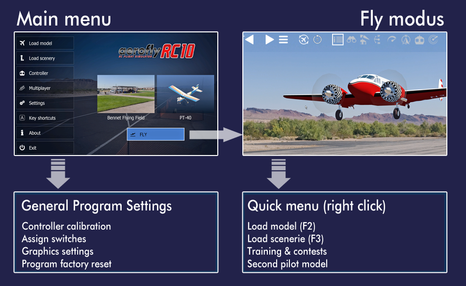
4. The two important menus of the RC10 at a glance
The menu navigation of the RC1o is greatly simplified without sacrificing the functions and settings of the RC8 or RC9.
The graphic below shows the simplified structure of the main menu and flight mode. All program-relevant settings can be accessed via the main menu, and all settings important for flying can be accessed directly via flight mode and the quick menu.
5. Activate the program
After the first start, the aeroflyRC10 must first be activated so that all models and scenery can be used. Activation is tied to your PC and is completely anonymous and only has to be carried out once. The product key required for activation is divided into 5 blocks of 4 characters each. It was made available to you as a download when you purchased it or is printed on the DVD.
If your aeroflyRC10 has not yet been activated, you will see this on the home screen. Click the yellow text button to activate.
Activation is quickest if you activate it directly in the aeroflyRC10. Enter your product key and then click “Activate now”.
Offline activation: If the PC on which you want to install the aeroflyRC10 does not have an Internet connection, please also enter the product key and click on “Activate now”. Information will now appear on how you can activate the program offline. Please follow the instructions in the program. This activation is not a solution if you receive an error message when activating from the program. If there is an activation error, please check this LINK page first
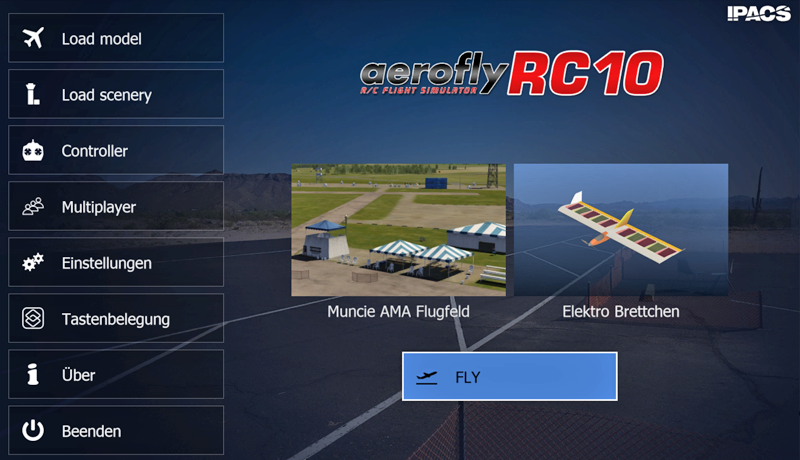
Immediately after starting the aeroflyRC10 via the desktop icon, you will reach the main menu shown on the right. Here you make the basic program settings.
You can use any control device with a USB port to control the aeroflyRC10. You can use an IKARUS Flight Controller in the same way as an IKARUS USB interface to connect your own remote control transmitter. If you do not initially have a control device available, you can initially fly with a mouse and keyboard for an initial test. (gas with W and S)
6.1 Setting up the control system
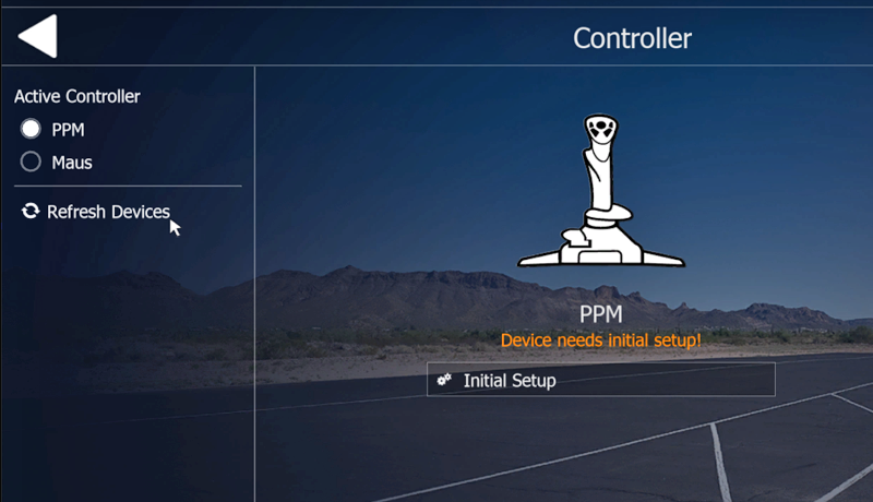
Then start the aeroflyRC10 and click on “Control” on the blue start screen.
If you have not yet learned a control device, the dialog shown on the right opens for setting up a new control device.
First click on Refresh: By clicking on Refresh you can search for the currently connected control devices.
Select the control device that you want to set up for the first time and then click on “Initail Setup”.
You will now be automatically guided through the further setup of the control device.
Step 1: Select Device Type
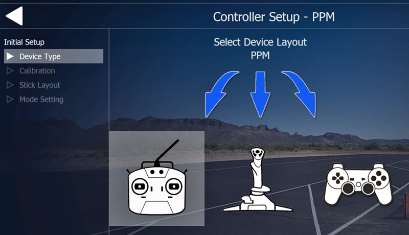
Select the type of control device here.
Click on the transmitter symbol on the left for all RC transmitters and USB GameCommanders. Click the middle icon for all flight simulator joysticks, the right one for gamepads. For precise model flying, USB game controllers or USB interfaces for your own RC transmitter are recommended.
Step 2: Calibration
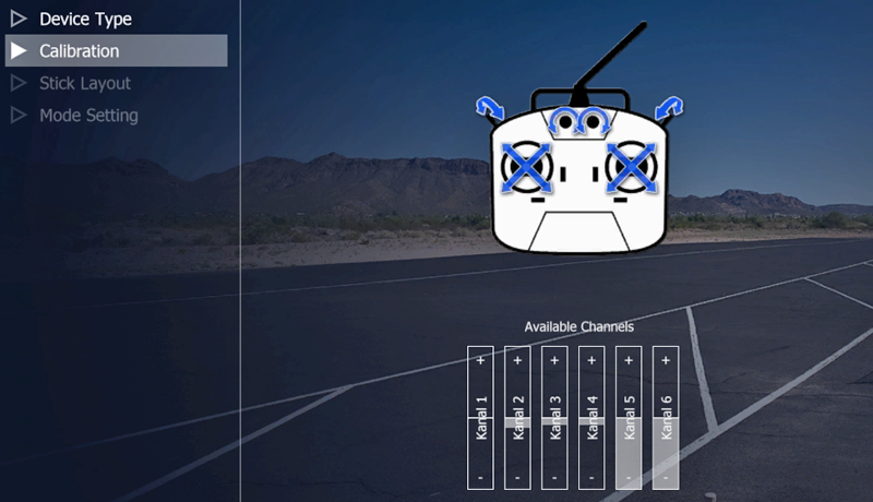
The aeroflyRC10 works with various interfaces and GameCommanders. In the next steps you will learn the paths of the joysticks and possibly switches. The control mode is not yet relevant. Just follow the instructions on the screen and move all sticks to all 4 corners and move the switching elements
Note: Leave the throttle stick vertical at the end (half throttle).
The aeroflyRC10 can later only use those switches and additional channels that were calibrated here. With an RC transmitter, the additional channels must first be set up in the transmitter (channel switch). Only what comes out of the transmitter and is calibrated here can later be used as a transmitter in the aeroflyRC10.
When you have moved all the encoders and no more bars shake across the full bandwidth, click continue.
Step 3: Stick layout
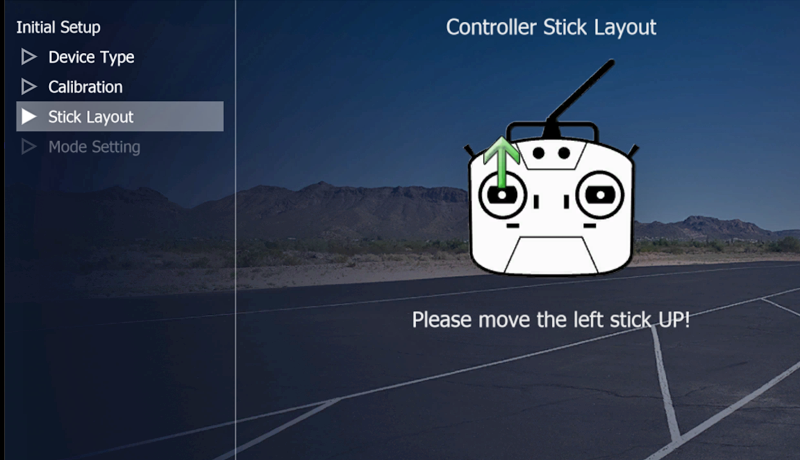
In this step you will learn the arrangement of the 4 stick movements. Therefore, you must strictly follow the instructions as to which stick should be moved in which direction. You will only determine the control mode in the next step.
Note: If an arrow disappears immediately after it appears and one of the 4 arrows is skipped, then there was an error in Step 2. Most of the time it is an unassigned input element (switch or encoder) whose bar in Step 2 is still full Bandwidth “shakes”.
Step 4: Set control mode
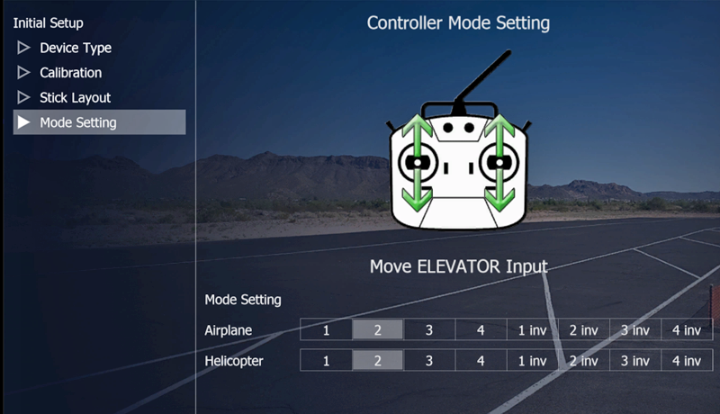
In the aeroflyRC10 you can fly in all 4 control modes, even with the throttle inverted idle position. In this step, set the desired control mode 1 to 4 by clicking on the band for the airplane and helicopter. “Inv” means a reverse idle position. You can check the correct setting by moving the joysticks.
Note: Any switches and additional channels may not yet be assigned here.
Click “Finish” to save the settings and complete the initial setup.
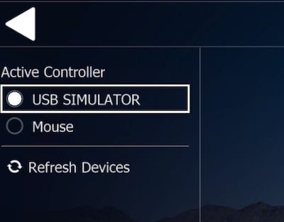
6.1 Control with the mouse and keyboard
If you don’t have a control device at hand, you can initially fly in the aerofly flight simulator with just a mouse and keyboard. To do this, first activate the “mouse” in the “Control device” menu
Key assignment with the “mouse” as TestController:
Gas: “W” and “S” buttons
Rudder: “Q” and “E” keys
Chassis: “G” key
Fold button “F”
6.2 Main menu
In the main menu of the aeroflyRC10 you can make the most important program settings.
Load model and scenery
Calibrate controller: See 6.1
Setting up multiplayer: See 10.1
Basic settings: menu language settings, simulation settings (6.4)
Key assignment: This opens a list of all shortkeys stored in the program. In chapter 10.6. You can find this list in A4 size to print out.
Exit: This button saves all settings (model, scene, control unit calibration and then closes the program
Fly: If you click on Fly, you switch to the flight operation display.
6.3 Main menu -> General settings
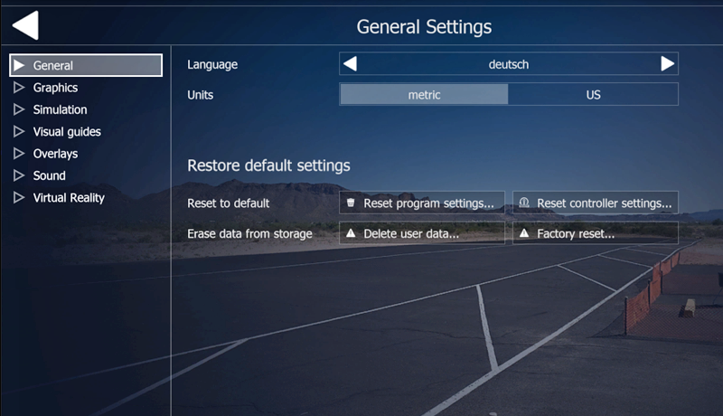
Selection of one of the 10 menu languages
Program reset: You can use the Restore buttons to reset specific settings in the aeroflyRC10 to factory settings
Restore to default: Reset all settings, including graphics settings, model favorites list, controller setup
Reset Program settings: Reset only the program settings ???
Reset Controller Settings: Reset controller settings only
Delete User Data: Reset the user directory
Factory Reset: Reset all settings, including graphics settings, model favorites list, controller setup
Units: In the aeroflyRC10 there are displays, for example, for the height or speed of the models. Here you can change the desired unit system.
6.4 Main menu -> Graphics settings
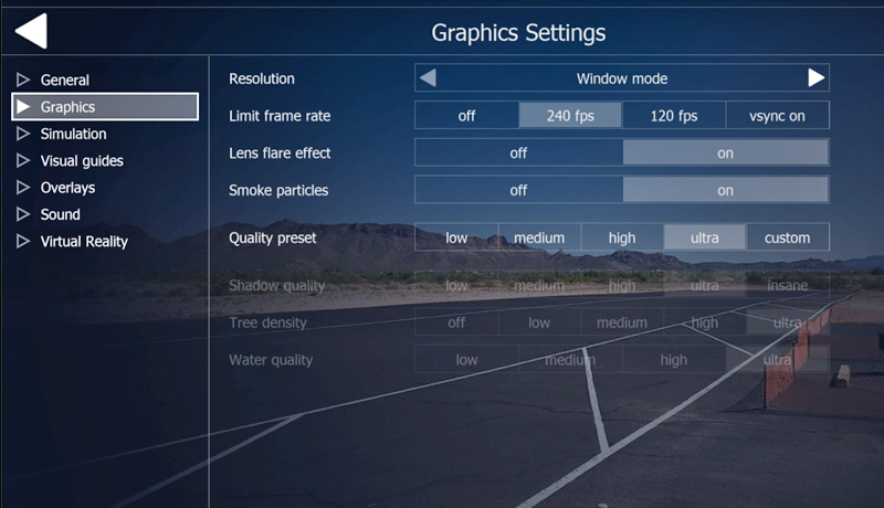 A rather low quality setting for shadows, trees and water can significantly reduce the load on the graphics card.
Use one of the presets from “low” to “ultra”. Only when you select “individual” are all settings released for your own setup. We recommend starting with low settings initially. If the graphics card doesn’t get too warm, you can gradually increase the resolution.
6.5 Main menu ->Simulation settings 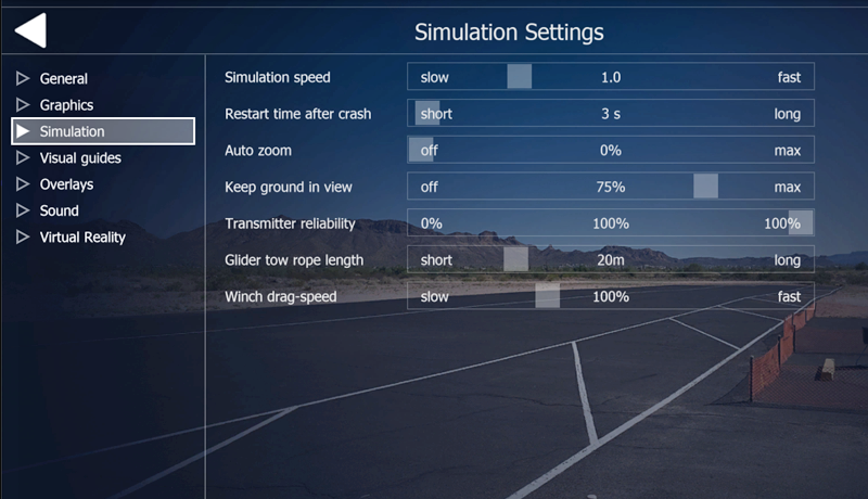
Simulation speed: The value should always be 1.0. You can only make slow PCs perform better by increasing the simulation speed, because the FPS rate primarily depends on the graphics card. However, when training certain flight maneuvers, it can definitely make sense to slow down the simulation to a value of 0.7.
Time for restart after a crash: Set the time after which a model is reset to the previously saved starting position after a crash.
Auto zoom: When auto zoom is activated, the observer’s field of view is automatically regulated depending on the model distance. If the model is close to the observer, the auto-zoom function adjusts the field of view to wide so that you can see a lot of the surroundings and then better prepare landings or avoid obstacles.
Height dependence: Due to the limited field of view, it is sometimes difficult to see the height of the model relative to the observer. When height dependence is enabled, the model shifts up or down when the model is above or below the observer height. Many pilots unconsciously fly directly above their heads in the simulator, precisely because of the limited field of vision. With height dependence enabled, the model would be at the top of the monitor when the model is exactly above the observer.
Transmitter reliability: If you want to put yourself under a certain amount of stress while flying, you can turn down the reliability. This leads to increasingly severe control failures.
6.6 Main Menu ->Visual Guides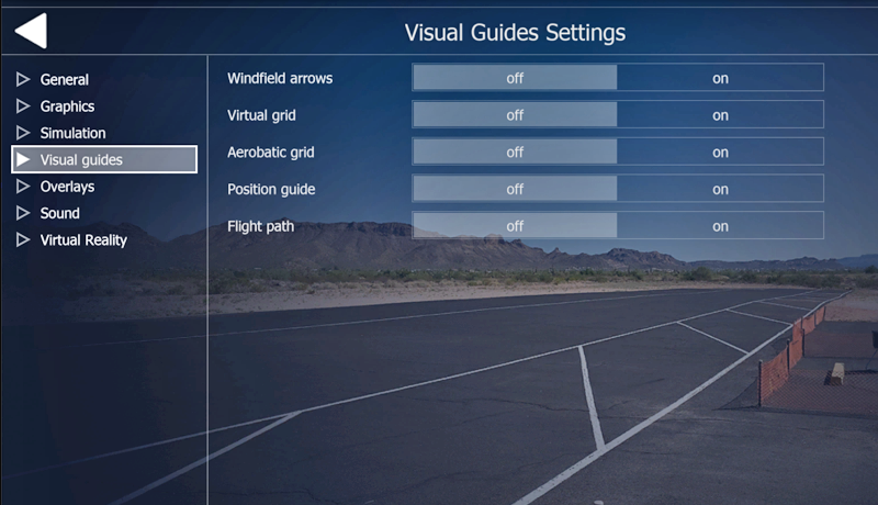
Additional displays such as the wind field with thermals can be switched on and off in this menu.
TheVirtual Grid is a cylindrical grid that provides orientation regarding flight altitude and distance to the location.
The AerobaticGrid is a grid for controlling the entry and exit height of the figures in aerobatic training.
ThePosition Guide indicates the flight altitude and position above the ground.
TheFlightpath visualizes the flight path and can be used for aerobatic training.
6.7 Main menu -> Overlay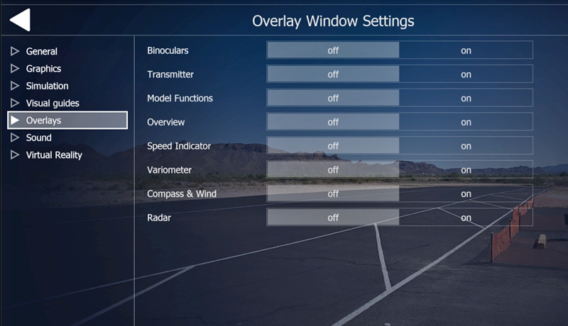
In the aeroflyRC10 you can display additional functions in small, semi-transparent windows. The binoculars help beginners to reliably recognize the flight attitude regardless of the distance.
The radar provides a simple graphical representation of the flight area with the orientation of the runway. A help for the correct landing layout.
In the View menu or via the quick selection menu, you can display the following instruments and information as small transparent windows:
Flight Aids: Binoculars, flight information, transmitter, model functions, and field radar
Instruments: Compass/wind, variometer, airspeed indicator and landing aid (???)
Note: After activating this menu, the windows appear at preset positions in flight operations. However, they can be arranged according to your wishes.
6.8 Main menu -> Sound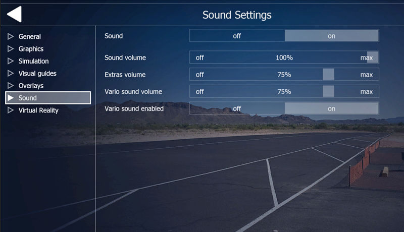
The volume of the individual sounds can be adjusted individually here.
Please note that computer system sound settings cannot be overwritten by these settings. The system sound must therefore also be ON and, if using a sound card or sound system, must have been set up and tested beforehand.
6.9 Main menu ->Virtual Reality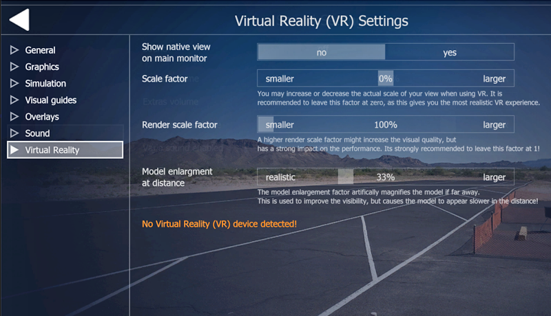
These settings are only visible when you start the aeroflyRC10 in VR mode (2nd desktop icon) and can only be used if you have previously installed your VR headset on the PC
Show normal view: This slider changes the display of the window on the PC monitor in VR mode. You have the choice between a split screen and a one-piece monitor image.
Scaling factor: These values influence the display in the headset and should initially always remain at the preset values
Render Scale Factor:
Model magnification: In the VR headset, this value can be used to reduce the optical reduction of the model as the distance increases. This zoom is not active at close range and improves attitude detection as the distance increases. When set to the maximum value, an effect can occur that makes the model feel sluggish when flying. In this case, reduce the value gradually until a good compromise between inertia at greater distances and good attitude detection is achieved.
7. Load flight model (F2)
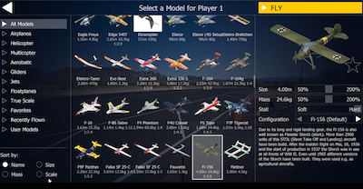
You can access the Load Model menu via the main menu or directly in flight operations with the right mouse button and the quick menu.
Filter models: On the left in the column you can filter by model type and sort all models by name, size or weight.
You can put together the “Favorites” folder yourself by clicking on the transparent star in the preview image. If this appears filled, the model can be found in the favorites.
7.1 Scaling flight models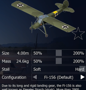
Below the preview image you will find the scaling of the models between 50% and 200% of their original size. Use the upper slider to first scale the model size. When changes are made, the weight (lower slider) initially changes automatically. If you also want to make an additional change to the mass after scaling the size, you can “override” the suggested change in weight using the second slider.
After calling the model, the changes were saved automatically. The next time you call up the model, you will find the model you modified again.
7.2 Preset flow stall
Below the preview image you will find a 3rd slider for the stall of the models.
If this feature can be used on a model, the slider can be adjusted in the range from “soft” to “hard”. If the function is not required for a model, the slider is grayed out and cannot be operated. The value setting is saved depending on the model
7.3 Load drive variants or model setups
The aeroflyRC10 has many models with different configurations. If a model has a configuration, you can access it using the two arrows < > choose.
Model setups: Some aerobatic models offer a choice of normal or acro
Drive configuration: Different drive variants are available for some models (electric / combustion engine)
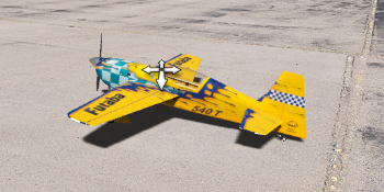
7.4 Load model with 4D prop (reverse thrust) 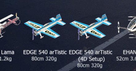
The selection of a model with a 4D prop is done as an independent model, shown on the right in the picture using the example of Addiction
7.5 Determine model as favorite
If you click on the star in the preview image, it will turn completely yellow and indicate that the model is now also saved in the favorites folder. Clicking on the star again deletes the model from the favorites folder.
8. Load scenery (F3)
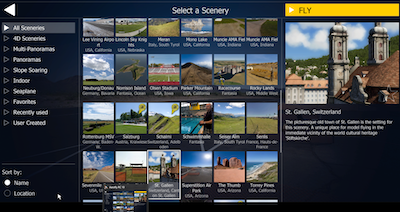
You can access the Load Scenery menu via the main menu.
Available competitions
The preview images contain a series of small white icons. These show directly which competitions are available in a scenery. In the detailed view, the competition symbols are replaced by letters.
Difference between photo scene, multipano scene and 4D scene
Please note that photo scenes show a viewpoint from the model pilot’s point of view. In multipano scenes, several of these viewpoints are available to you in one scene. 4D scenes, on the other hand, are completely artificially generated scenes in which you can move completely freely.
In the photo, multipano and 4D scenes you can determine the wind, wind direction, wind strength, turbulence, thermals and many other parameters yourself.
In the 4D scenes you can also adjust the time of day. The easiest way to do this is to repeatedly press the T key (time forward) or Shift+T (time backwards).
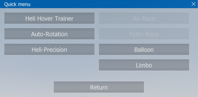
9. Quick selection menus (Quick Menu)
When flying, you have 2 menus and function keys to quickly access all settings relevant to flying
F2: Load model
F3: Load scenery
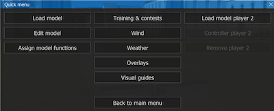 Right-click gives you quick access to the most frequently used functions:
Right-click on any area of the screen while the quick selection menu shown on the right opens.
It allows quick access to the model change and, above all, the settings, wind, weather and overlays that can be used for flight operations.
10. Night flight 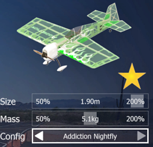
There are two things you need to keep in mind for the night flight in the aeroflyRC10. You need a 4D scene with the time of day setting and ambient lighting and a model with night flight lighting.
After loading the scene, you can change the set time of day with “T” or “Shift+T”. Initially choose a twilight light rather than a full night to get used to recognizing attitude via the lights.
You can recognize models with the night flight option by the “Nightflight” configuration below the preview image.
11. The different camera modes
aeroflyRC10 offer you four different camera modes with which you can observe the models. These camera modes are activated using buttons 1 to 4 or alternatively via the “View” menu.
Note: Only the “Fixed observer position” camera mode is available in the photo sceneries.
11.1 Setting the field of view
In all camera modes you can use the ‘Z’ and ‘Shift+Z’ keys to reduce or enlarge the camera’s field of view. Use the ‘Shift+Z’ key to reduce your field of vision, i.e. H. the model becomes larger, but at the same time you see less of the landscape, as if you were looking through a telephoto lens. With the ‘Z’ key you enlarge your field of view, so you see more of the landscape, but the model becomes smaller. Depending on the distance and size of your monitor, you may have to experiment a little to find your optimal value.
11.2 Selection of the starting position
Each landscape offers different starting positions for the models. In 4D landscapes there are also other positions for the observer. To switch to these different positions, use the ‘V’ and ‘B’ keys. Once you have found a desired position, you can always start the model from this point by pressing the space bar.
To reach the different observer positions in the MultiPano sceneries, press the page up/down buttons. The ‘V’ and ‘B’ keys only switch between the different model positions in these scenarios.
The different modes are described below:
11.3 Fixed observer position (key 1)
This is the standard mode for all model airplanes. The camera stands in a fixed position and looks at the model. In this mode, the following buttons are also available to you in the 4D sceneries for further settings:
Left/right arrow key: Use this to rotate around the current model position.
Arrow key up / down: You move towards the model or away from the model.
Image up/down: The observer is set higher or lower.
11.4 Follow mode (button 2)
In chase mode you fly behind the model. Just imagine that you are connected to the model by an elastic rope. This mode is only available in the 4D scenes
Arrow key up / down: Arrow key up / down: The virtual rope that connects the camera to the model is made shorter or longer, allowing you to fly closer to the model or further behind the model.
11.5 Model camera (button 3)
In this mode, the camera is at a freely adjustable position around the model and moves with the model’s center of gravity. This mode is well suited for observing the model in flight. The camera does not track rotations of the model around the longitudinal and transverse axes. Taking off and landing is a bit tricky in this mode. The following keys are available to you in this mode. This mode is only available in the 4D scenes
Arrow key left / right: Use this to rotate around the model.
Arrow key up / down: You move towards the model or away from the model. You can move away from the model up to a maximum of four model radii.
Image up/down: The observer is set higher or lower. You then look at the model on top or up at the model.
11.6 Cockpit mode (button 4)
In this camera mode you are permanently connected to the model, i.e. H. the camera performs all the movements that the model does. There are further sub-modes in cockpit mode. Simply press button 4 repeatedly to activate the different positions.
1. The first cockpit mode (pressing button 4 for the first time) places the observer at a point relative to the model and you always look at the model’s center of gravity. Use the left/right/up/down arrow keys and the page up/down keys to rotate around the model.
2. The second cockpit mode places the observer in a fixed position and looks in the direction of flight. In this mode your own model is not visible.
3. Some models optionally have additional fixed cockpit positions with a fixed viewing direction. In these modes you can change the viewing direction using the left/right/up/down arrow keys and the page up/down keys.
12. Moving camera and model
You can use the mouse to easily move the camera and the model, for example to move the model to a desired starting position.
Note: Please note that the following functions are only available in Fixed Observer Position mode (F5 key) or Run mode (W key).
 Move camera
Press the left mouse button on any free area. The mouse pointer becomes a symbolic eye with directional arrows. Hold down the left mouse button and move the mouse to pan the camera. To look at the model again, press F5.
Position model
Move the mouse to the center of the model. The mouse cursor now becomes a cross made of arrows. Press and hold the left mouse button and move the mouse to move the model. Movements up or down push the model further away or closer.
Rotate model
Move the mouse to the edge of the model. The mouse pointer becomes a symbol of rotating arrows. Press and hold the left mouse button and move the mouse to rotate the model.
Raise/put down model
Move the mouse over or under the model. The mouse pointer becomes a symbol of arrows pointing up and down. Press and hold the left mouse button and move the mouse up or down to raise or lower the model. You can also move it to the right and left at the same time.
13. Set control functions
All basic settings of a new control unit must be made in advance in accordance with Chapter 6
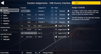 13.1 Assignments
The other functions such as switches and additional channels are now assigned in the “Assigments” menu.
Assign special functions
The other special functions are displayed under Channels 1-4 and can be assigned by clicking in the line.
The selection of special functions depends on the currently selected model.
Available as possible assignments
Toggle 3-Way:
Toggle On/Off:
Virtual/analog
Analogue mode (if a channel is assigned to the function)
Standard: The full range of the channel is used to control the function.
Top Half: Only the top portion of the channel is used.
Lower half: Only the lower part of the channel is used.
Example: To be able to control two different functions A and B with a rotary control or 3-step switch on your transmitter, assign the corresponding channel to both functions and then select the upper half of function A and the lower half of function B.
Digital mode: (when keys/knobs are assigned)
On/Off switch: Pressing the button switches between on and off.
3-way switch: Pressing the button switches between -100, 0, +100, etc.
Hold = On: Only while the button is pressed does the function go to +100
Step ‘+/–’: The left button moves the function stepwise to the left (–)
the right button to the right (+)
Move ‘+/–’: The left button moves the function continuously to the left (–)
the right button to the right (+)
Virtual Analog: Simulates an analog channel using one or two buttons.
The longer a key is held, the larger the deflection becomes.
If the button is released, the deflection decreases.
By pulsing the button faster/slower you can achieve and maintain a larger/smaller deflection.
Examples: Flaps or swing sashes can be moved in and out continuously using the ‘Move +/–’ setting and by assigning two buttons. Alternatively, you can use the ‘3-way switch’ setting to switch through three positions with just one button.
It makes sense to define a towing hook as ‘Hold = On’ so that it is only opened briefly when you press the corresponding button.
A wheel brake can be defined as a ‘virtual analogue’. The longer you hold the button, the stronger the braking effect becomes. If you only want to brake lightly, you have to stutter on the button.
Inv (9)
For analog channels, you can reverse (invert) the direction of movement here by checking the box.
13.2. Set model type dependent functions
In the column on the left you can pre-select whether you want to set the functions of a fixed-wing model, helicopter or glider.
13.3 General
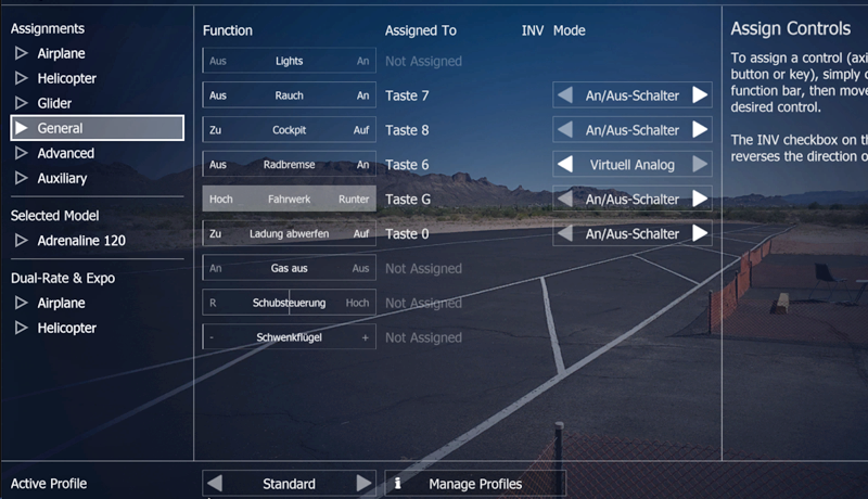
All functions that are used across models are assigned in this menu.
13.4 Advanced 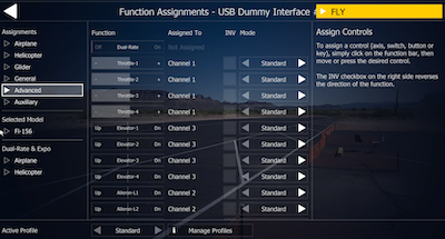
In this menu it is possible to split channels that are still assigned to a single channel of the control unit in 13.1. This means that, for example, the QR channel and the WK channel can be separated into 2 servos each in order to control a 4-flap surface completely individually via the transmitter with your own RC transmitter. This split requires prior programming in the transmitter and recalibration of the transmitter so that the aerofly recognizes the inputs on the additional channels. The Advanced menu is aimed at everyone who wants to make and try out all the settings via the transmitter. Flying multi-motes and four-flap surfaces is also possible using the normal settings with one channel per function!
Expo/Rate
Expo can be selected between 0 and 100 and is used to control the zero position more precisely while still maintaining the maximum deflection.
Expo = 0: No change; Stick travel is directly converted into servo travel.
Expo = 100: Small servo travels can be controlled very precisely (with long stick travels).
Settings up to approx. Expo = 50 are recommended. Higher values only make sense in extreme cases.
Rate can be selected between 20 and 150 and specifies the maximum deflection of the function.
For example, Rate = 40 means that the servo travel at full stick deflection will only be 40% of the normal travel.
Dual rate
This feature allows you to toggle between two different Expo/Rate settings during flight.
Note: Dual rate functionality is supported by most modern remote controls. You can program dual rate in the transmitter as usual and don’t have to set anything else here. If you are using a GameCommander or do not want to change the internal programming of your transmitter, you can also simulate dual-rate directly in the flight simulator.
Assign the function as usual by clicking on the ‘D-R’ bar and then moving a switch or pressing a key. Alternatively, select a channel directly from the list.
Now when you move the assigned switch (or press the assigned button), all Expo and Rate values jump back and forth between the standard setting (black) and the dual rate setting (blue).
Now set the desired values for Expo and Rate for both switch positions (dual rate on and off).
13.1 Setting the controller for the helicopter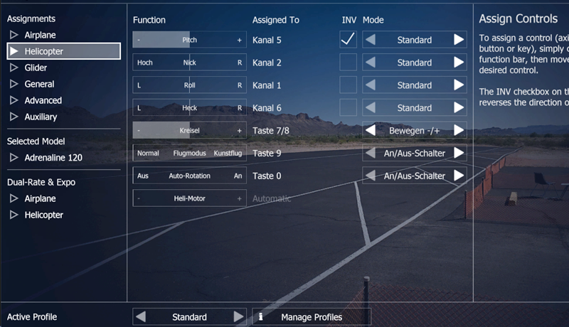
aeroflyRC10 offers automatic engine control for all helicopters in the standard setting.
Heli engine on ‘Automatic’ (default):
‘Automatic’ means: The motor revs up automatically and, depending on the model and flight mode, is automatically controlled depending on the pitch channel.
Flight mode ‘Normal’:
Positive pitch results in more gas, negative pitch results in less gas (linear increasing gas curve).
This mode is used for engine run-up and hovering.
Flight mode ‘Acro’ (Idle Up):
Both positive and negative pitch result in more gas (V-shaped gas curve).
This mode is suitable for inverted flight and aerobatics.
Autorotation:
Rotor is separated from motor. No gas is accepted.
Manual setting for helicopter motor
If you would like to control the speed manually or use your transmitter’s helicopter throttle curves, please assign the ‘Heli Motor’ function to the channel of your transmitter on which the motor signal is sent.
The ‘flight mode’ function is then irrelevant as you control the motor directly. Autorotation works as usual and separates the main rotor from the engine.
13.2 Setting the controller for (motor) gliders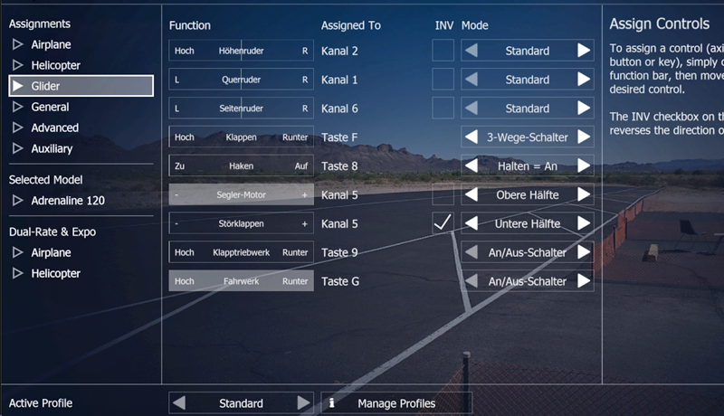
The default default is the following:
Throttle stick from the middle upwards: engine control (if the sailor has an engine)
Throttle stick from the middle downwards: airbrakes (or ‘butterfly’)
Key ‘6’:
Extend/retract folding engine
The function for the folding engine can be found further down in the list under ‘Special functions’.
Manual setting for sailors (‘Advanced channel settings’)
Pilots with a transmitter that has enough free controls will prefer the following setting, which can be selected manually in the Advanced Channel Settings window:
You place the auxiliary motor control on a free switch or rotary control on the transmitter (here channel 7).
Now you can set the brake flaps to the full stick travel. (Set the function mode from the lower half to ‘Standard’. Check the box next to ‘Inverse’ if you want to pull the stick to brake.
Depending on your preference, the retraction and extension of the folding engine can be assigned to the same channel that controls the engine, or you can use another channel for it.
14. Two-player mode (via quick menu / right mouse button or “m”)
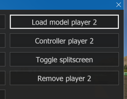 To fly with two people on one computer, proceed as follows:
- First open the quick menu and click on “Load 2nd model”
- Then load the model for the 2nd player.
- After loading the 2nd model, the screen will automatically split into 2 halves
- Now open the quick menu again and click on “Controller 2nd player”
- Now select one of the previously calibrated controllers for the 2nd player
14.1 Screen splitting
By default, the screen area is split vertically once a second model is loaded. The left half is for player 1, the right for player 2. You can change the division to “horizontal” (top/bottom) or cancel it completely using the ‘S’ key or in the “View” menu under “Image division”.
14.2 Glider tow
To perform a glider tow, see 15.9. Sailor tow
15. Competitions and training modes
Select your desired training or competition to open the corresponding window. There you will receive further information and help.
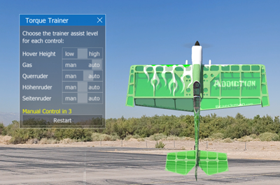
15.1 Torque trainer
Snap to Observer button
The torque trainer influences the alignment of the model using the “Align to observer” button in the settings window. If the checkbox is checked, the torque trainer always rotates the model around the longitudinal axis so that the top of the model faces you as the pilot. The function makes it easier to get started with torquing.
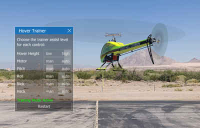
15.2 Hover trainer
The trainer slowly revs up the engine to avoid rotating the model.
You can use the sliders to determine how much the trainer supports you on the motor, pitch, roll, pitch and tail channels. ‘Manual means you have full control over a channel. The initial position of the controls is ‘Trainer’. You can move the sliders further towards the middle position and learn to control the model while the trainer helps you with small corrections. When the trainer has control of the tail, he will attempt to orient the model with the tail towards you.
15.3 Target landing
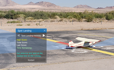
Then take off and try to land as many times as possible at the finish line within the time limit. The points achieved are added up.
15.4 Autorotation landing
 Load a helicopter model and scenery that features an autorotation competition. Then select the menu item “Autorotation Competition”. A circular target marker appears and the model is automatically positioned at the target point.
The “Graphic Help” button displays a column that gives you an orientation for the target marking during the autorotation approach.
Take off and climb to the required height (usually 20 m). Then go into autorotation by switching the appropriate channel. In the standard configuration this is the ‘0’ (zero) key. Then land as close to the center of the marked area as possible. You can perform multiple landings within the time limit and the points will be added together.
15.5 Pylon Race
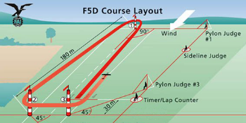 Load a suitable model and scenery that features a pylon race. Select the “Pylon Race Competition” menu item. A course of 2 or 3 pylons is set up and your model is brought into a starting position.
You get an overview of the route in a 4D scenery. You can use the “Show Help” checkbox to show or hide the route.
Press “Start” in the competition window or the space bar to start the race.
Penalties: To make the race more interesting, a player who misses one or more cones will not be immediately disqualified. Instead, the penalty is implemented in such a way that the player in question does not have gas available for the duration of the penalty time.
15.6 Air Race
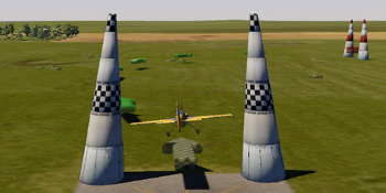 Load a suitable model and a 4D scenery that has an air race. Select the “Pylon Race Competition” menu item. A course is set up with several gates (airgates) and your model is brought into a starting position.
You will first see an overview of the route. You can use the “Show Help” checkbox to show or hide the route.
Press “Start” in the competition window or the space bar to start the race.
The blue gates must be flown through horizontally. Otherwise you will receive a time penalty depending on the lean angle. Please note that the gates are ‘flown through’ and not ‘overflown’. If you fly higher than the tops of the pylons, the goal is considered missed.
The red gates must be taken in knife flight (one wing must point upwards).
The chicane is a slalom through 3 or more pylons. Follow the green arrows, they point to the correct line. The flight attitude is irrelevant here.
Penalties: To make the race more interesting, a player who misses one or more goals will not be immediately disqualified. Instead, the penalty is implemented in such a way that the player in question does not have gas available for the duration of the penalty time.
15.7 Heli precision flight
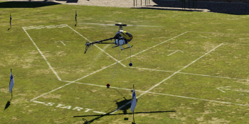 Download a helicopter model and scenery that offers precision heli flight. Select the menu item “Heli precision flight”. A route is recorded and your model is brought into starting position.
Fly through the marked route in the direction of the arrow. The red ball must always be in contact with the ground within the track, the blue ball must remain in the air.
Tip: Make the model easier to control when hovering. To do this, set Expo from 0 to approx. 50 in the advanced channel settings and reduce the overall deflection (rate) to approx. 60%. You can also fly at reduced speed by manually switching the engine to a channel.
The point requirement is usually 360 points. Every mistake leads to a point deduction. A pirouette can be flown at the corners marked with crosses to get extra points. A pirouette against the direction of rotation of the main rotor counts double.
Competition and timing begins when the red ball crosses the starting line. The time limit for the task is usually 60 seconds. If the time is exceeded, points will be deducted. A perfect flight is rewarded with bonus points.
15.8 Dynamic Soaring
First load a suitable glider model (e.g. ‘Intention’) and a scenery that enables dynamic soaring (e.g. Creek Island, Norrison Island, Parker Mountain).
Then select “Dynamic Soaring” from the “Extras” menu. This places the sailor at a predefined starting position and automatically sets the appropriate wind to achieve dynamic soaring. You can select this menu item multiple times to go through all preset dynamic soaring positions.
Note: Dynamic Soaring is operated on the leeward side of the slope (left in the picture). The starting positions are chosen so that the model is thrown against the wind, i.e. towards the windward side (to the right in the picture). (Otherwise the sailor could starve to death in the leeward direction). Start by picking up the wind, turning as you go, and then drop down the leeward side to fly back below the boundary layer (in the lee of the mountain). Near the ridge you pierce the boundary layer again from bottom to top, turn again and push down into the lee, etc.
15.9 Glider tow (F-tow)
 First load a glider model (e.g. ‘Intention’) and a towing machine (e.g. ‘Wilga’) “as a second model”.
Then press the ‘Tab’ key to automatically move the models into position and connect them with a tow rope. The towing machine must first roll carefully until the rope is taut, then accelerate more.
Note: If no F-towing positions are predefined in a scenery, the models will be left in their current positions and connected to the rope if they are on the ground and close enough together.
15.10 Winch start and assistant
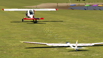
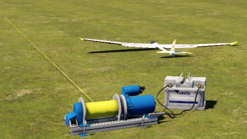 For glider models, the flight simulator offers two options: the winch start and the assistant who drops the model. Once a suitable model (glider) is loaded, go through all possible starting positions as usual using the ‘V’ or ‘B’ keys. Once you have found the desired position, press the space bar to start. If you want to repeat the start, simply press the space bar again.
Note: You can use the program menu under
“Simulation” / “Simulation settings” set the pulling speed of the winch and thus adapt it to the model.
Note: If there are no winch launches or starting positions with an assistant in a scenery, you can still use the ‘J’ or ‘H’ keys to raise and drop the model by hand 2m or 50m into the air.
16. Set wind (via quick menu)
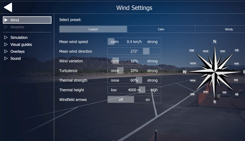 has an elaborately simulated wind model with full terrain dependence (up and down winds, deflection, slipstream and leeward vortices). In addition, there are statistically fluctuating wind strengths and wind directions, turbulence and a dynamic thermal simulation (formation, growth, rising and dissolution of thermal tubes).
Under “Simulation” / “Simulation Settings” you will find the following options under “Wind” to adjust the wind according to your wishes:
Wind presets: Select one of the basic settings specified for each scenery here.
Medium speed: Select the wind speed here. Please note that this is an average value. Depending on the variation (see below) and the terrain, there may be completely different wind conditions at your current position.
Middle direction: Here you can specify the direction of the wind. (see also variation)
Wind variation: This setting specifies how much the wind fluctuates in both direction and strength over the long term. 0% corresponds to a very constant wind (e.g. sea wind) 100% is an extremely fluctuating wind. 20% is the default value.
Turbulence: This setting affects the short-term disturbances in the wind. 0% corresponds to a completely trouble-free ‘laminar’ air flow. 100% is extreme fluctuations. 20% is the default value. Please note that the turbulence increases as the wind strength increases. Turbulence of 50% in very light winds will hardly be noticeable, while the same setting in very strong winds can have extreme effects.
Thermal: Here you can set the strength of the thermal updrafts. Please note that the thermals also depend on solar radiation, terrain and wind strength. Regardless of this setting, sunny ‘southern slopes’ always offer better updrafts than shady areas. Strong winds will suppress the formation of thermals.
Show wind field: If this box is checked, directional arrows and thermal tubes will be displayed during the simulation, showing the current wind conditions. Green arrows signal updrafts, red arrows should be avoided by the glider pilot.
Note: With the wind rose you can adjust the direction and strength of the average wind with one click. At the same time, you can use the dynamic preview (green arrow) to assess how strong the wind will be at the current camera position and how much it will fluctuate.
17. Simulation settings (via quick menu)
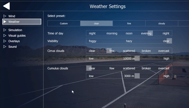 offers the unique opportunity to freely set the time of day and weather conditions. With just a few clicks of the mouse you can switch from a sunny morning to a cloudy evening atmosphere with sunset and further to night and fog. In many scenarios you can also activate special functions such as an orientation grid, F3A grid or the position display.
17.1 Flight conditions (via quick menu)
Time of day: Use this slider to select the time of day (position of the sun) in 4D scenes. You can also change the time of day directly while flying by repeatedly pressing the T (time forward) or Shift+T (time backwards) key.
Weather preset: Select one of the presets given for each scenery here.
Haze/Fog: Here you can adjust the density of the haze and thus the visibility. Values to the right of the middle position correspond to denser fog.
Cloud Details: You can individually turn each cloud type (available in the scenery) on and off and influence its parameters.
Note: Settings with a high cloud density can require a lot of computing power and can dramatically affect the smoothness of the simulation (especially on older computers).
17.2 Sun glare effects (via main menu)
You can use the main menu and “Graphics” to activate a backlight effect that makes flying even more realistic. Please note that this effect increases the demands on the graphics card
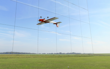
17.3 Virtual grid (via quick menu)
 The virtual grid serves as an orientation grid. It’s like a big, round tower with the pilot standing on the ground in the middle. The grid simplifies orientation in landscapes with few clouds and helps maintain a constant flight altitude.
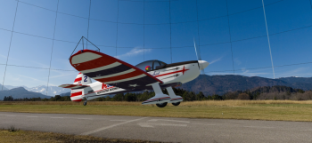
17.4 F3A grid (via quick menu)
 The F3A grid serves as a guide for aerobatics. It’s like a big net stretched behind the airfield. The horizontal lines are used to control the flight altitude, the vertical lines are used as a training aid for vertical passages in aerobatic maneuvers.
17.5 Position display (via quick menu)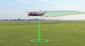
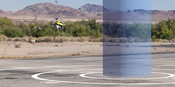
Select “Visual Guides” from the quick menu. With “Show position aid” you can switch on a position display that uses a transparent column to mark the position of the model above the ground. The flight altitude is also displayed. With this information you can display, you can specifically practice landing approaches, for example.
17.6 Show flight track (via quick menu)
Select “Visual Guides” from the quick menu. Under “Flight Track” you can activate a two-color band that follows the aircraft behind it. This will mark the flight path. This display is used to control a clean flying style and is a good aid for beginner training, as well as for aerobatic training or slope flying.
17.7 Setting the sound (via main menu)
From the main menu, select Settings ->“Sound”. Here you can deactivate the sound across the board or set the extras individually.
Under the control for the overall volume of all sounds you will find individual controls for the volume of the extra sounds, Vario and music.
Note: the sound of the Vario can only be heard if you have activated the Vario in the program menu under “View” / “Show Vario”. In the “Vario” instrument you will also find a button at the bottom right to switch the Variosound on or off.
18. Record and play back flights
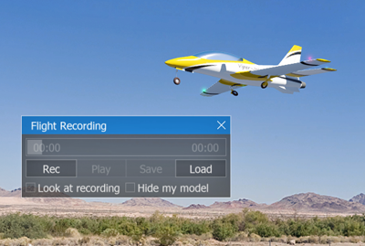 aeroflyRC10 allows you to easily record and replay your flights. You can also make your recorded and saved flights available to other aeroflyRC10 users. To start recording, select the “Recording Window” sub-item in the “Recording” menu to make the following window visible. You then have the following options to choose from:
filename
Enter a name here under which your recording will be saved.
Description
Enter text to describe your recording. (Optional)
Rec: Starts a new recording.
Play: Plays a recording.
Pause: Pauses playback.
Stop: Stops recording or playback.
Load: Here you can load a saved recording again. Please note that only recordings taken in the current scenery can be loaded.
Save: Saves the current recording with the file name entered above with the description entered above.
18.1 Exchange flights with other users
If you want to share your recorded flights with other aeroflyRC10 users, simply copy the files in the “Recordings” directory. Then copy these files to the other user’s “Recordings” directory.
19. Multiplayer mode 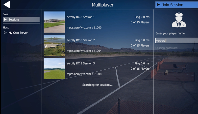
In the aeroflyRC10 multiplayer mode you can fly with up to 16 pilots at the same time on different PCs. The computers should preferably be connected to each other via TCPIP and LAN cable. A connection via the Internet is also possible, but this requires at least a DSL 2000 connection or faster.
19.1 Language support (VoiceChat)
The aeroflyRC10 flight simulator also offers voice support (VoiceChat) for multiplayer sessions. This means you can communicate with the other pilots while flying. This is particularly useful in order to be able to coordinate better with several players. All you need is a microphone.
However, for best quality and to avoid feedback effects, we recommend using a headset (headphones with a microphone). In this way, the flight sounds are not transmitted as voice output with feedback. You can fine-tune the speakers and microphone sensitivity directly in the aeroflyRC10 or in the Windows control panel.
19.2 Logging into a multiplayer session
A central multiplayer server is constantly running on the Internet and registers and manages all ongoing multiplayer sessions. Now if you want to fly with other players on the Internet, click on “Search Internet” to search for an ongoing session. The central multiplayer server then sends you all known multiplayer sessions, which you can then find as an overview list in the upper window.
Important note: In order for aeroflyRC10 to find multiplayer sessions running on the Internet, UDP ports 7000-7020 must be enabled on your system. If you have a firewall or use a router, please enable these ports beforehand. You must allow both incoming and outgoing connections on these ports.
If you want to join a multiplayer session on the LAN, you can automatically search for the current aeroflyRC10 server by clicking on “Search in the local network”.
In the overview list you can see what kind of scenery is currently loaded, how many players are online and whether you need a password for the connection.
Connection speed: Under connection speed you can choose between LAN or Internet. If you have a connection via the Internet, you should also choose Internet here, as this significantly reduces the amount of data that is transferred compared to a LAN connection. Due to the higher transmission rate, more information can be transmitted on the LAN, which may make the flight movements of other players appear more fluid.
19.3 Multiplayer info window
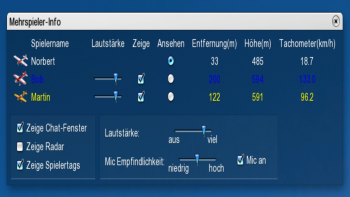 For a better overview of all registered players, there is the multiplayer info window. By default, this opens automatically after you have successfully logged in. It gives you an overview of all players and useful additional displays such as speed, altitude and distance.
The individual fields of the window are explained below:
Player name: Here you can see the player name and a small icon of the current model that the player is currently flying.
Volume: If a multiplayer server supports VoiceChat, you can individually adjust the voice volume of a player here.
Show: Here you can selectively hide certain players completely so that you can no longer see or hear their model.
View: If you want to permanently view the model of a specific player, simply click on the corresponding button here. If you are in chase mode in a 4D scenery, you will then be behind the player model.
Distance: The distance of the model from your current position.
Height: The height of the model above ground.
Speedometer: The speed of the player model.
In this window you also have the option to globally adjust the volume for the voice output of all players. With “Mic Sensitivity” you can set the volume at which your microphone becomes active. If you don’t want anyone to hear you, uncheck “Mic on”.
After the successful connection, the chat window also opens in which you can send short text messages to other players. Here you can also see when a player registers or changes model.
In order to keep track of which pilot is where, especially in 4D scenery, you can display the radar window in which you can see the positions of the other pilots. To do this, click on “Show Radar” in the “Multiplayer” menu. For further assistance, the player name, model speed and height difference are displayed above each model of a network player. If you don’t need this display, just click “Show Player Tags” in the Multiplayer menu.
19.4 Settings during a multiplayer session
When you are in a multiplayer session, you will no longer be able to adjust all of the settings that aeroflyRC10 usually offers you. If you are the first user (the so-called master) to log into a multiplayer session, you can freely adjust environmental conditions such as wind, time of day, fog and clouds. The other users then automatically notice these changes. However, changing the landscape is not possible.
However, every user can change their model at any time. However, avoid changing models too often, otherwise this could cause delays for the other players, who then also have to load your model so that it can be displayed.
19.5 Delays in multiplayer sessions
In connection with multiplayer sessions over the Internet, an important point should be addressed here:
aeroflyRC10 sends the position of a model to the other players approximately 4 times per second. Sending this data packet over the Internet takes on average between 20 and 200 milliseconds, depending on the connection speed and quality. This means that when a player receives my position, you are already in a different place. A further delay is added because aeroflyRC10 needs to interpolate the position of a player model to achieve smooth movement. If you only show a player’s model at the four positions that arrive per second, it would be a very jerky representation.
As a rough guide, you can assume that the positions of the other players are about half a second behind.
If you look at e.g. For example, if you are in chase mode and you are flying just in front of another player, the time delay may mean that the other player sees themselves in front of the other player.
19.6 Setting up a multiplayer server 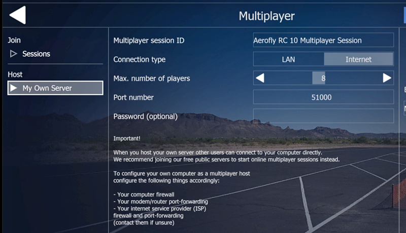
In order to set up a multiplayer session yourself, the aeroflyRC10 server application must be running. This can be done either directly in aerofly or via the independent application “aeroflyRC10-Server”. You can start the multiplayer server easily and conveniently by clicking on “aeroflyRC10 multiplayer server” in the aerofly program group. A simple console window will open, which you can then simply leave open. Alternatively, click on the “Set up server” entry in the Multiplayer menu in aeroflyRC10. The following window appears:
Session name: Enter the name of the multiplayer session (session) here. Other users will then see this name when they search for an aeroflyRC10 server on the LAN.
Player name: Enter your name here, under which you can see the other players.
Max. number of players: Here you can limit the multiplayer session to a certain number of players. The default value is 8. The higher the number of players, the faster your internet connection should be so that you can still play smoothly. A LAN connection is usually sufficiently fast for up to 8 players at the same time.
Port number: The port number is important if you want to play aeroflyRC10 over the internet. Certain Internet providers may block some port numbers. If this is the case, simply enter a different port number here. Make sure that you enable this port on your firewall for incoming and outgoing connections.
Connection speed: Under connection speed you can choose between LAN or Internet. If you are connecting via the Internet, you should also choose Internet here, as this reduces the amount of data that is transferred compared to the LAN.
Password: Optionally, you can specify a password so that only certain users who know the password can log in.
Voice chat: Optionally, you can also allow your aerofly server to allow voice chat. If you don’t want this, simply uncheck the box. A little less data is then transferred, which may be an advantage with slower Internet connections. However, the data overhead is not very large.
The first player in a multiplayer session (the so-called master) determines in which landscape and under which environmental conditions such as time of day, visibility and wind speed will be flown. Except for the current scenery, all parameters can be changed by the master during an ongoing session.
As soon as an aerofly server is running, other players can log in.
20. The model editor
The model editor allows you to easily and conveniently modify the properties of a model and adapt it to your needs.
Note: Due to the many setting options and parameters, you can quickly adjust a model to such an extent that proper flying is no longer possible. Should this happen, you can always return to the standard settings provided (see 20.4).
20.1 Open model editor (via quick menu)
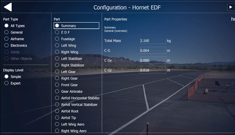
20.2 General
On the left side of the window, all available components are displayed in a folder structure. Click a part or group of parts to display it on the right for editing.
Reset all Reset changes to all components since the window was last opened.
Save as Save model and enter a new name and description.
You can also delete existing settings here.
Save Save model with current name.
Close the test editor and test changes to the model.
Cancel Close the editor and discard all changes since the last time you opened the window.
Reset part Reset changes to a component.
Note: You cannot overwrite the aeroflyRC10 standard models supplied. A new name (e.g. Edge 540T (edited)) will be automatically created when you select “Save”.
20.3 Saving and deleting changed models
Select “Save as” in the model editor or the “Save model as…” menu item in the “Model” menu to open the dialog. Here you can save your current settings or remove configurations that you no longer need after setting them.
All existing configurations of the model are displayed in the list. The supplied aeroflyRC10 standard configurations are displayed in gray; you cannot change or delete this configuration.
Save: Enter a name and a short description of the set configuration and press “Save”.
Delete: Select the configuration in the list with a mouse click; the configuration will then be highlighted in blue. Then press “Delete” to remove the configuration.
20.4 Loading modified models
In the loading dialog (see 7. Loading aircraft models) your modified and saved models appear under “Available configurations”. From there, select the configuration you want to load.
21. Contact and support
If you have any questions or problems with aeroflyRC10 please contact:
IKARUS
Byk-Gulden-Str. 21
78467 Konstanz
Germany
E-Mail: support-de@aerofly-rc.com
Internet: www.ikarus.net