


Butterfly position in the aeroflyRC
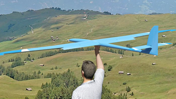 On this page we explain the two basic options for controlling a four-flap wing and the butterfly position using the glider model “Caliber” as an example.
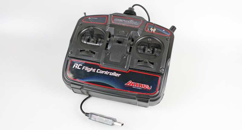
Option #1 shows the default settings for all users of an IKARUS FlightController with item number #3036012.
Option #2 shows all settings to control the four-flap wing with 2 x ailerons and 2 x flap via a RC transmitter individually, e.g. also to use all transmitter-internal mixers such as Aileron -> Elevator.
Option #1: Control the four-flap wing with an RC flight controllerThis option does not initially require any individual settings, as the aeroflyRC automatically extends the butterfly position from the halfway point of the “throttle stick” during installation. |
 |
| If you want to use the entire stick travel and not just one half of the travel, you can change the control of the “spoilers” from “Upper half” to “Standard” in the aeroflyRC main menu under “Control unit” / “Assign controller” under “Glider” as shown in the photo. This will extend the butterfly over the entire stick travel. Note: This change causes a changeover in all models. | 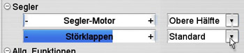 |
Option #2: Control the four-flap surface completely via an RC transmitter
This option is aimed at advanced users of the aeroflyRC and assumes that you are familiar with the basics of the menu of your own RC radio. Please also note that these individual channel assignment settings do not only affect one model in the aeroflyRC.
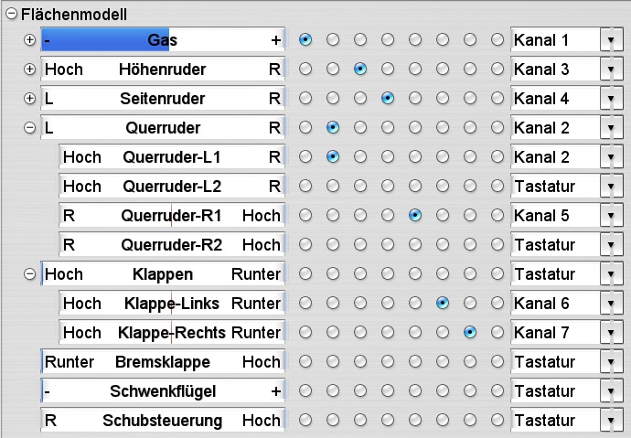
| 2.1 Radio and calibration: At first please create a new memory in the transmitter, in this case with the name “aerofly-Caliber”. In the basic menu of the transmitter, also set up 2 x ailerons and 2 x flaps and the required mixers. You must then repeat the calibration in aeroflyRC and check whether you can operate the two aileron and also the two flap channels via the transmitter. In this example, the two aileron are on K2 and K5 and the two flaps on K6 and K7. These four bars must already follow the transmitter inputs in this first step of the calibration! The direction is not important, but the bars must move and must no longer flicker. Finally, carry out all further calibration steps to the end and select the control mode there. |
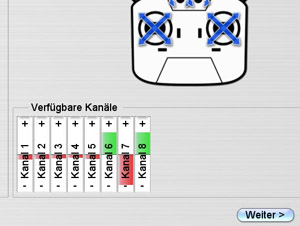 |
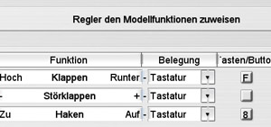
| 2.2 Switch off the standard flap function of the aerofly: Before you now manually assign the programmed transmitter channels for ailerons and flaps in the aerofly, you should deactivate the standard control of the flaps, as otherwise overlapping may occur. To do this, under “Control unit” / “Assign controller “, decouple the interference flaps from a transmitter input as shown in the photo and switch to “Keyboard”, for example. |
 |
| 2.3 Assignment of the channels in the aeroflyRC: Now load the “Caliber” model in the aeroflyRC and open the two lines for “Ailerons” and “Flaps” under “Control unit” / “Assign controller” using the plus sign. Now assign the channels of the ailerons and flap function manually in the table. In this example, these are: Aileron-L1 = channel 2 Aileron-L1 = channel 5 Flap-Left = channel 6 Flap-Right = channel 7 |
 |
| 2.4 Last settings: All 4 flaps should now follow the transmitter inputs. If one of the flaps is reversed, always use the servo reverse in the transmitter to ensure that all mixers run correctly later on. From now on, all control surface functions will be controlled directly from the transmitter. Including settings such as flap differentiation, “Brake -> Elevator” mixer or all other mixers. |