


 Flying with a Powerbox-Core on the aeroflyRC
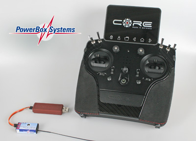
You have different possibilities to connect a Core transmitter from Powerbox-Systems to the aeroflyRC. In all cases you use your core receiver for a wireless transmission of the control signals.
Further down on this page you will find tips on the basic setting of the core for simulator operation.
Option #1: PPM sum signal up to 12 channels
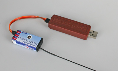 Using a patch cable you can connect the PPM output e.g. on the core receiver PBR-5S to the IKARUS-USB interface set #3031020.
The advantages of this solution are:
- The 5-channel PBR-5S receiver outputs 12 channels via the PPM signal. You therefore have a very large number of channels available for all functions!
- The receiver is supplied with power via the USB interface.
- The set contains the interface and the patch cable.
Option #2: Single channel mode and S.Bus
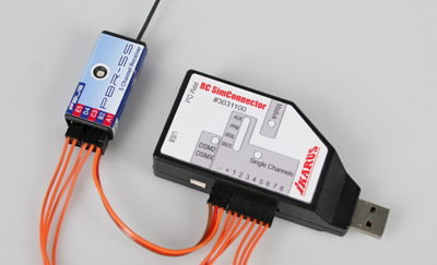
You can connect any 2.4 GHz receiver with at least 4 channels to the IKARUS RC SimConnector in single channel mode. Also one of your Core receivers. This solution transmits between 4 and max. 8 channels.
With 4 channels you can already fly throttle, elevator, rudder, aileron and all powered models, gliders, jets, helicopters and drones.
Optionally, you can also operate your Core receiver in S.Bus mode and then transmit all channels provided by the receiver to the RC SimConnector via a single patch cable.
Basic settings on the Core radio
 The Core from Powerbox-Systems offers many options for programming a RC model. In order to fly with a Core on the aeroflyRC, a memory only with few basic settings is sufficient for the beginning. Below we describe a solution for a successful start with aeroflyRC.
- Bind the receiver to the sender.
- Swipe up the main menu and create a new model memory.
- Assign a name such as “aeroflyRC”.
- When selecting the model types, select the symbol for an powered model, even if you want to fly gliders or helicopters on the aeroflyRC. Leave the selection for Delta and V-tail at “No” in any cases.
- In the next window you have to assign at least the four encoders for the basic functions throttle, elevator, rudder, aileron
If you want to control additional functions such as landing gear and flaps from the radio, you can also select additional sensors here. Create for flaps or landing gear in the aerofly in the core under “Special functions” e.g. Aux-1 and Aux-2 as encoders. The assignment to the functions is done later completely free in the aeroflyRC. -
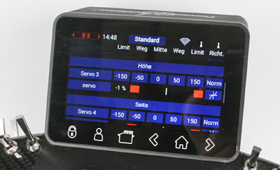
In the next window of the Core, you will now see all the functions that you have previously linked to an encoder. Now you have to assign a servo no. to all functions. If you want to use the model memory in the Core universally for all your Core receivers and all models in the simulator, then you should make sure that you assign the basic functions throttle, elevator, rudder, aileron to the servos 1 to 4.
With this basic setting you can now continue with the calibration in aeroflyRC.
Start the aeroflyRC and click in the main menu under “Controller” on “Search for a new controller”. Afterwards you should get the interface and the detected channel number reported and follow the further instructions for calibration. If you have any issues, please follow this interface test.
You will then find all details on the professional setting menu in the aeroflyRC manuals.